Home > Harmonic Robot Joint Actuator > M Series Robot Joint Module
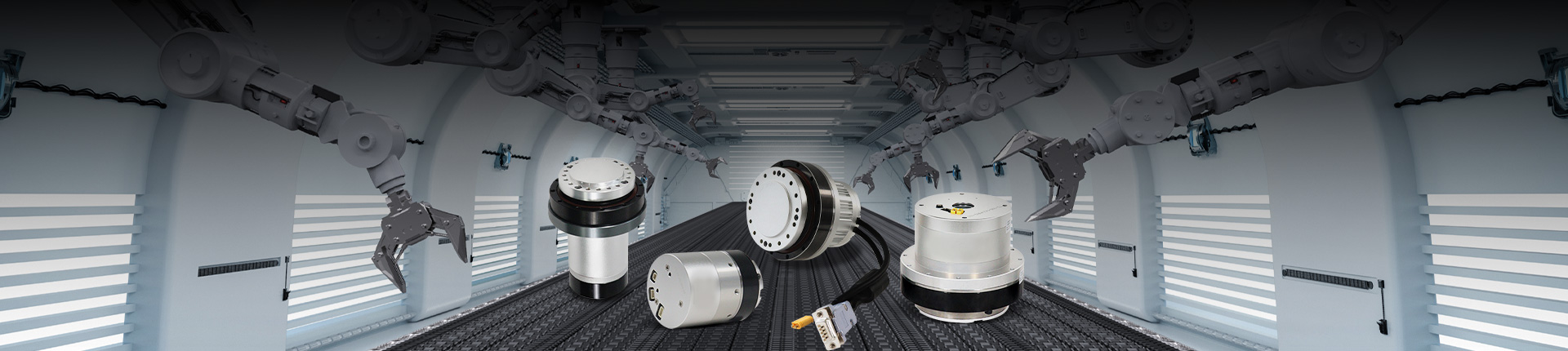
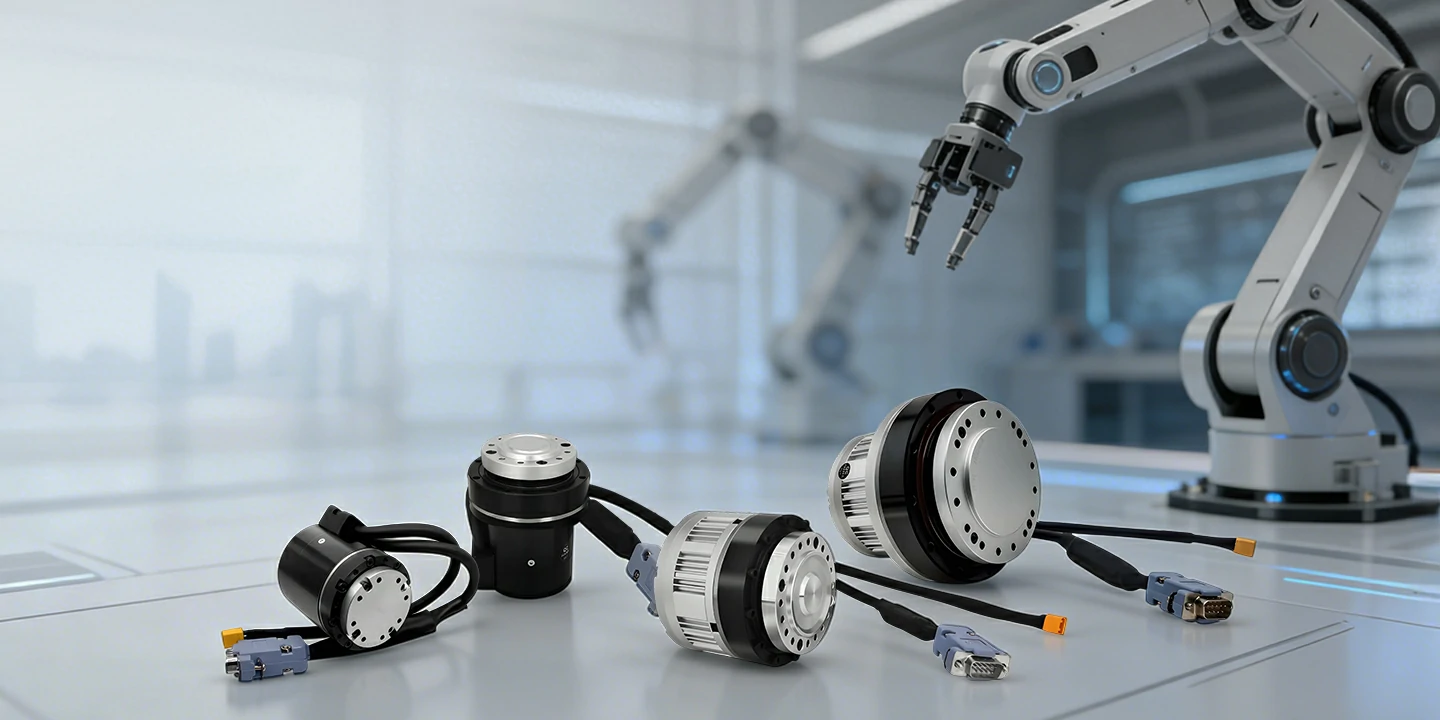
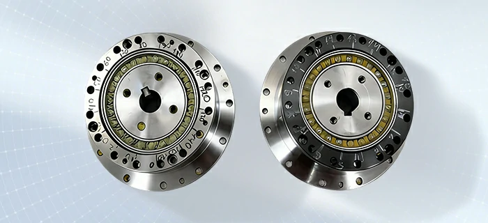
The robot joint actuators integrated DC motor , harmonic reducer , absolute encoder and high servo motor drive together , So M Series robot joint actuators make automated production easier and more efficient,can build the robot project soon, applications for various requirements .
The harmonic drive actuators have stable performance and fewer after-sales problems, making it the first choice for robot customers.
Max rated torque: 100NM
Peak Speed : 30RPM
Rated Voltage: 36VDC±10%
Communication: Canopen, Modbus,EasyCan
| Model | M8025E25B50/80/100L | M8010E17B50/80/100L | M4215E14B50/80/100L | M4210E14B50/80/100L |
| Motor rated voltage | 36VDC±10% | 36VDC±10% | 36VDC±10% | 36VDC±10% |
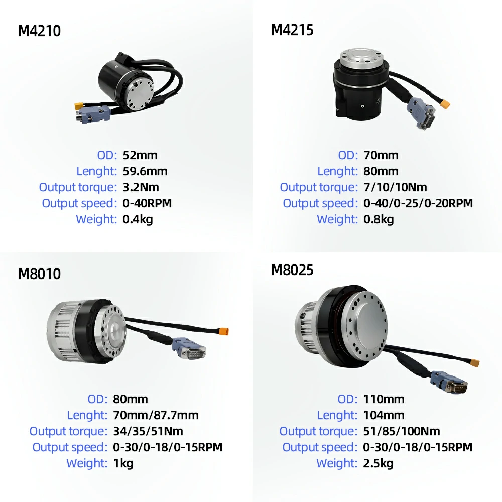
| Output torque | 51NM/85NM/100NM | 34NM/35NM/51NM | 7NM/10NM/10NM | 3.2NM |
| Output Speed | 0~30RPM/0~18RPM/0~15RPM | 0~30RPM/0~18RPM/0~15RPM | 0~40RPM/0~25RPM/0~20RPM | 0~40RPM |
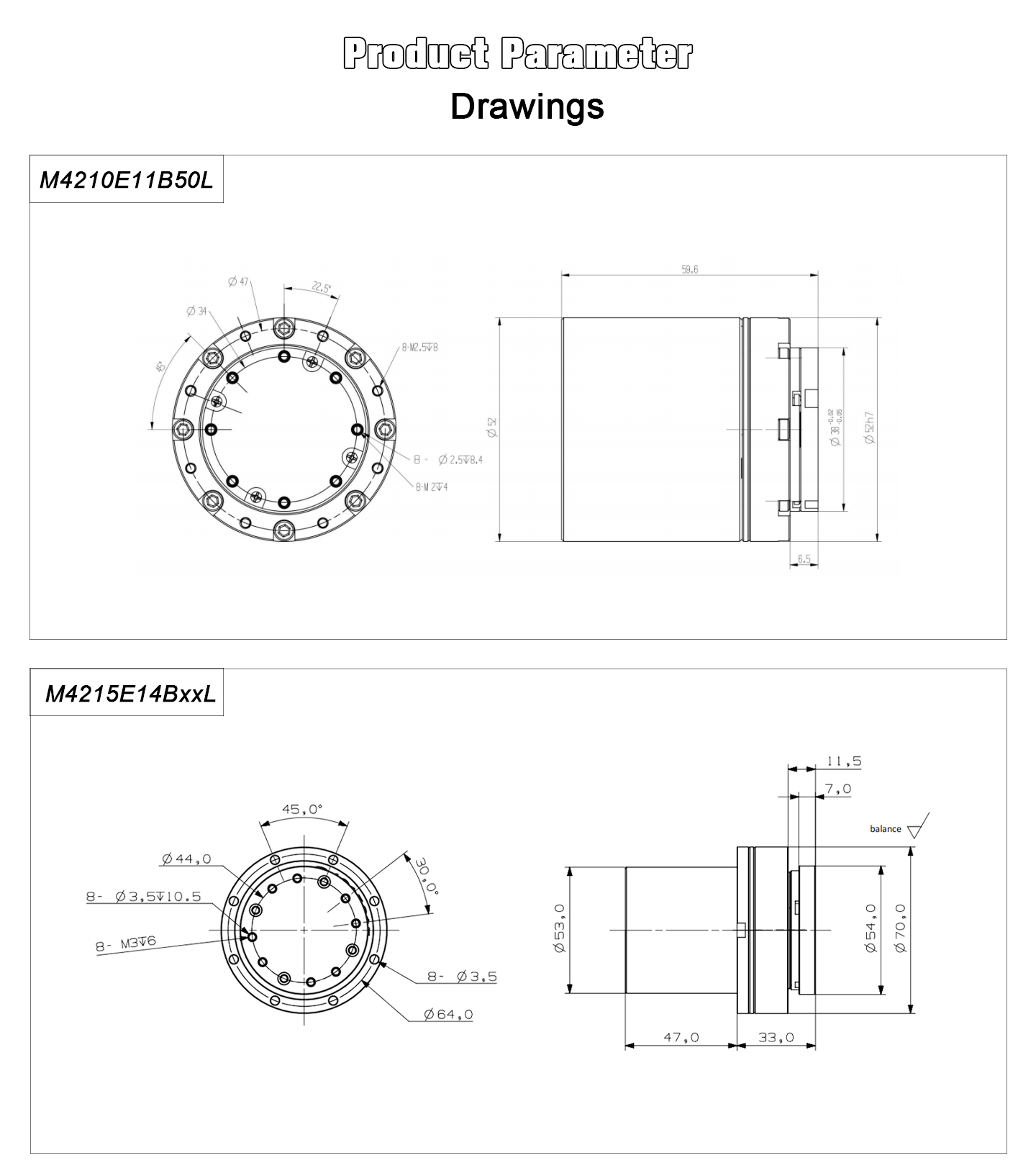
| OD | 110mm | 80mm | 70mm | 52mm |
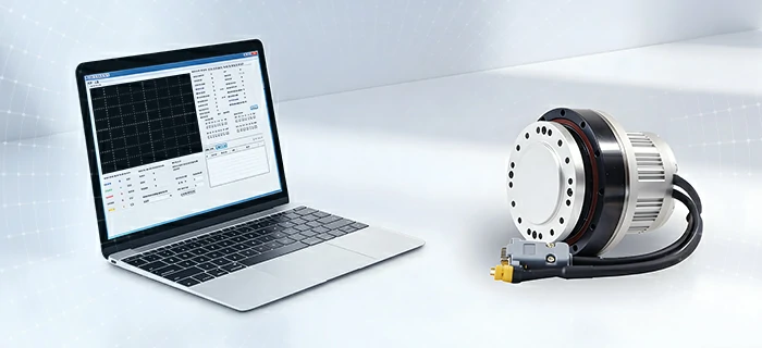
-Isolate CANopen communication according to CiA301 V4.2.0 specificationSupport SDO, TPDO, RPDO.
-Support speed mode, position mode (contour mode, interpolation mode)
-Support heartbeat production and consumption
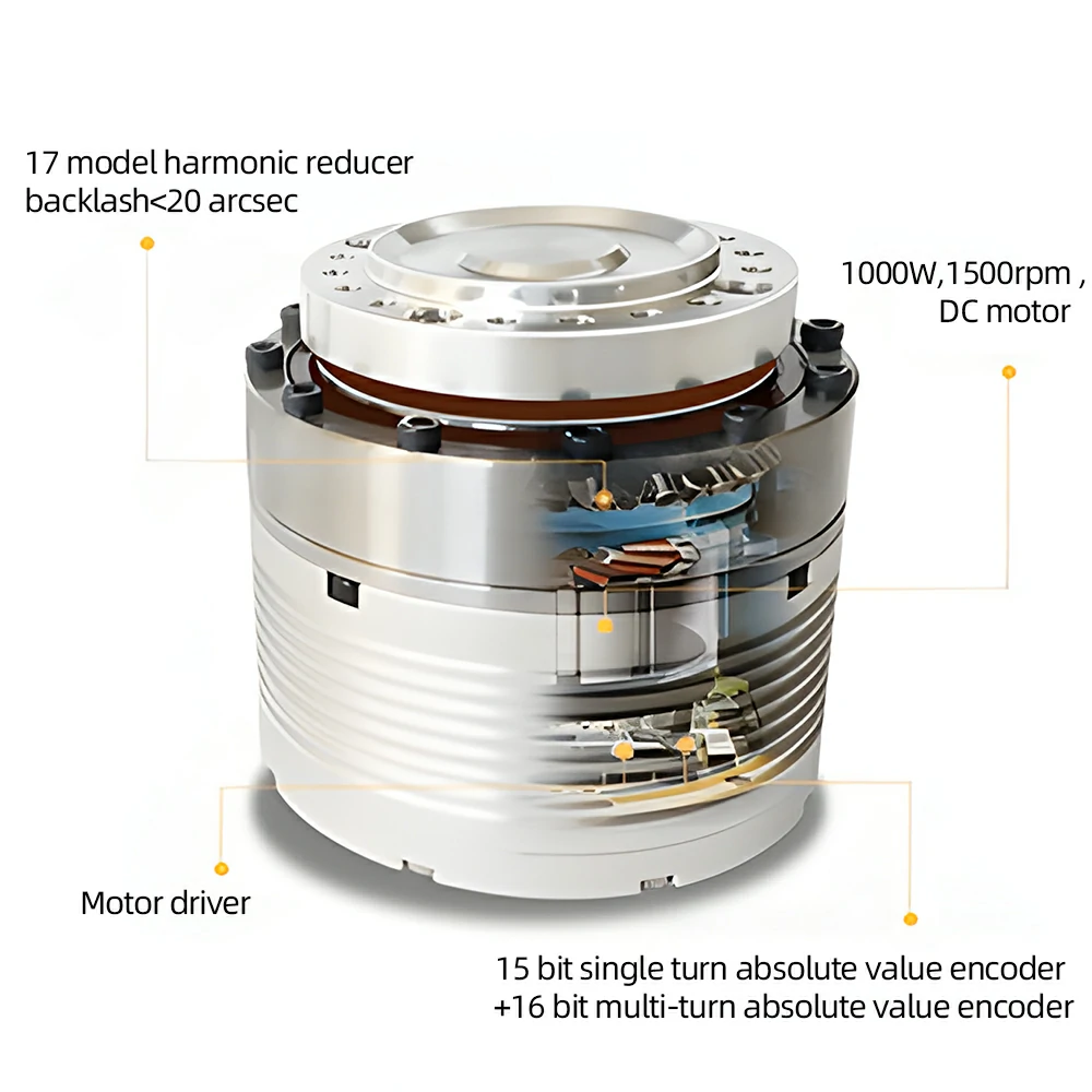
-15 bit absolute encoder, one lap pulse up to 32768.
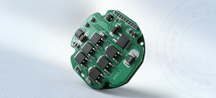
-Harmonic reducer, motor, driver and 15bit +16bit encoder are integrated.
-when the robotic joint motor is powered, there is a charging circuit inside to power the -battery.
--When the robot servo motor is powered off, the battery current consumed is only 0.07mA.
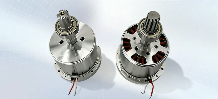
-Multi-Stage Direct Drive Architecture for Enhanced Torque Density
-High Torque Output with Smooth and Precise Motion Control
-Integrated Design for Efficiency and System Reliability
-High-Precision Harmonic Reducer
-Low Noise & Low Vibration Performance
-High-Speed Positioning Capability
-High Reliability for Continuous Operation
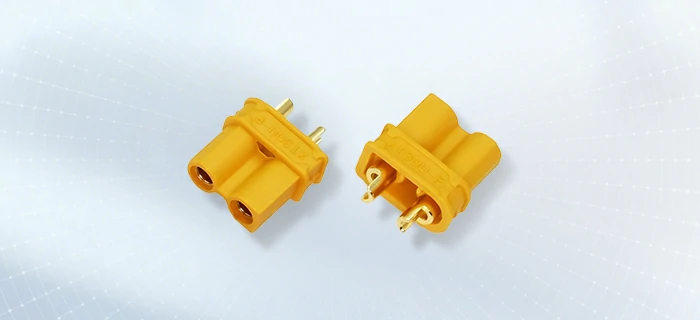
| Terminal Serial No |
Name | Function |
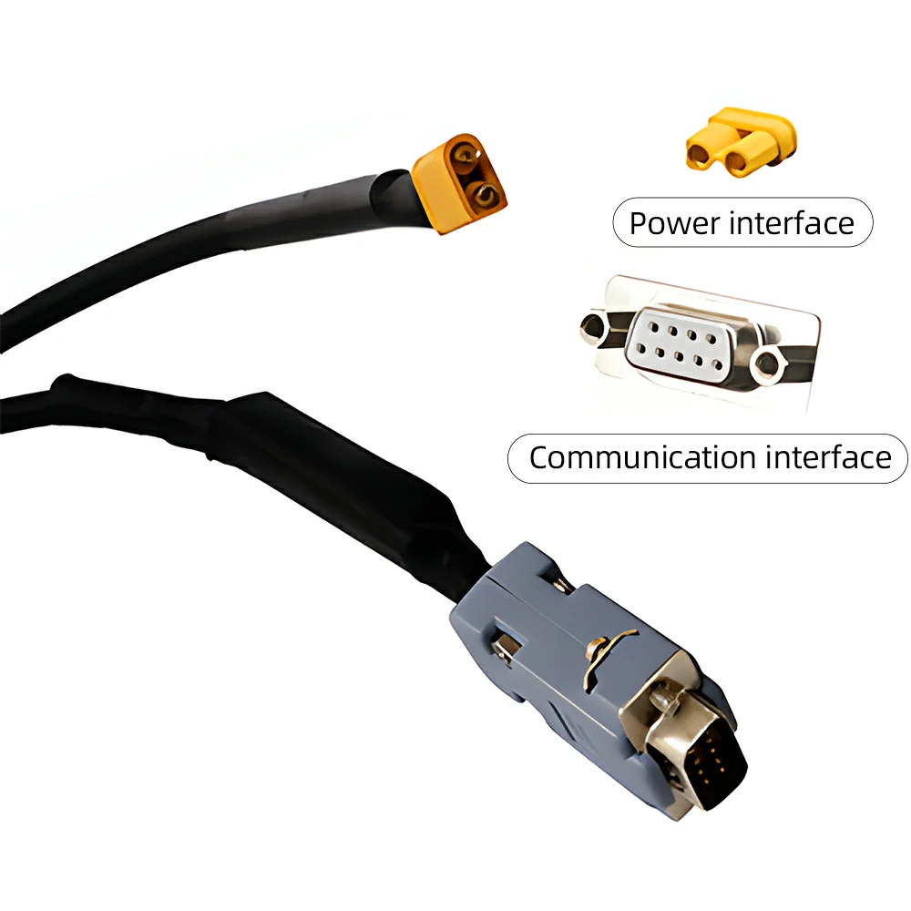
| 1 | +V | Positive DC Power +24V~36V. Negative and positive connections can either directly short the power supply or damage the driver |
| 2 | GND | DC power source. Negative and positive connections can either directly short the power supply or damage the driver |
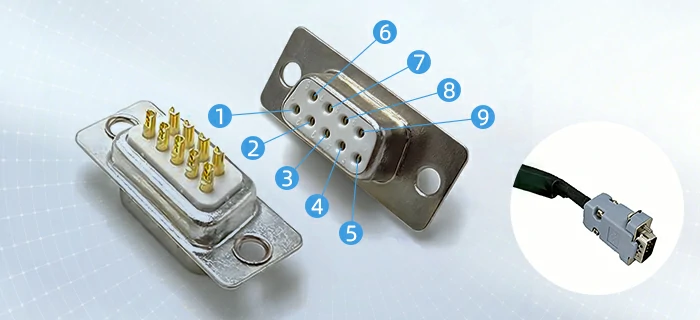
| Db9 Male head | ||||||||
| 1 | 2 | 3 | 4 | 5 | 6 | 7 | 8 | 9 |
| PU+ | PU- | DIR+ | DIR- | WR+ | OZ | COM | CANL | CANH |
| BLUE | BLUE BLACK |
GREEN | GREEN BLACK |
RED WHITE |
YELLOW | BLACK WHITE |
BROWN | WHITE |
| Terminal serial number |
Name | Function |
| 1 | PU+ | Pulse control signal: the rising edge of the pulse is valid; PU- is 3.3~5V at high level, and 0-0.5V at low level. For reliable response to pulsed signals, the pulse width should be greater than 1.2μs. If +12V or +24V is used, a series resistor is required. |
| 2 | PU- | |
| 3 | DIR+ | Direction signal: high/low level signal, in order to ensure the reliable commutation of the motor, the direction signal should be established at least 5μs before the pulse signal.DIR-3.3~5V at high level, 0-0.5Vat low level. |
| 4 | DIR- | |
| 5 | WR+ | Alarm signal output, the internal output is optocoupler NPN.Normally,it is in high impedance state, and it is connected to COM during alarm. |
| 6 | OZ | Encoder zero output. There is a zero signal optocoupler NPN output conduction signal. |
| 7 | COM | The output signal is common to the 485 power supply. |
| 8 | CANL | Can Communication port CANL, built-in isolated power supply |
| 9 | CANH | Can Communication port CANH,built-in isolated power supply |
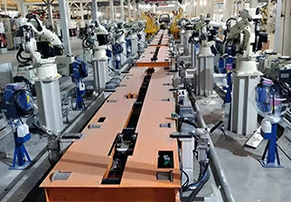
Fully automated production
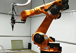 Welding robotic arm
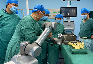 Surgical robot
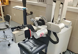
Medical rehabilitation robot
| Parameter | M4210E 14B50L |
M4215E 14B50L |
M4215E 14B80L |
M4215E 14B100L |
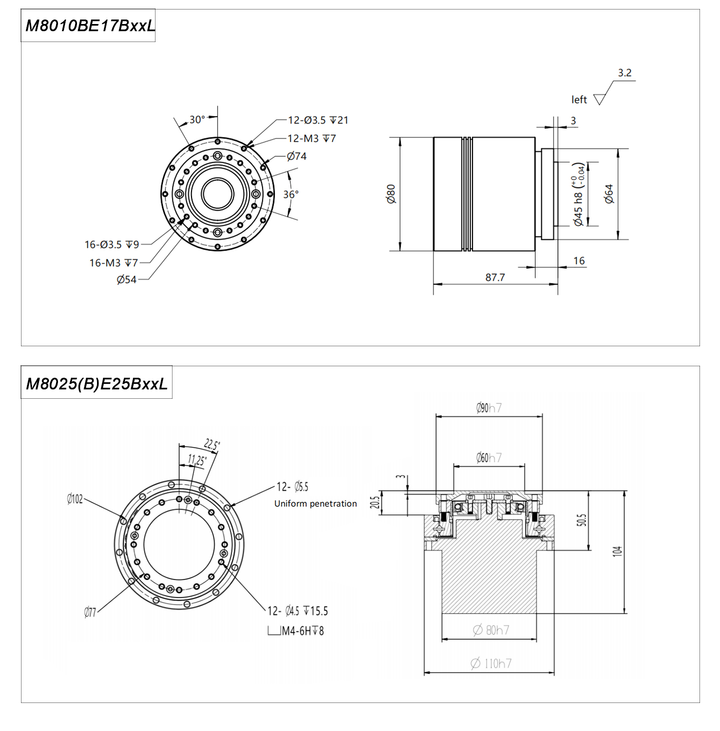
M8010(B) E17B50L |
M8010(B) E17B80L |
M8010(B) E17B100L |
M8025(B) E25B50L |
M8025(B) E25B80L |
M8025(B) E25B100L |
|
| Overall parameter | Motor rated voltage | 36VDC±10% | 36VDC±10% | 36VDC±10% | 36VDC±10% | 36VDC±10% | 36VDC±10% | 36VDC±10% | 36VDC±10% | 36VDC±10% | 36VDC±10% |
| Motor rated current | 1.5A | 2A | 2A | 2A | 3.5A | 3.5A | 3.5A | 7A | 7A | 7A | |
| Output torque after deceleration | 3.2NM | 7NM | 10NM | 10NM | 34NM | 35NM | 51NM | 51NM | 85NM | 100NM | |
| Weight | 0.4KG | 0.8KG | 0.8KG | 0.8KG | 1KG | 1KG | 1KG | 2.5KG | 2.5KG | 2.5KG | |
| Speed range after deceleration | 0~40RPM | 0~40RPM | 0~25RPM | 0~20RPM | 0~30RPM | 0~18RPM | 0~15RPM | 0~30RPM | 0~18RPM | 0~10RPM | |
| Reducer parameter | Reduction ratio | 50 | 50 | 80 | 100 | 50 | 80 | 100 | 50 | 80 | 100 |
| Rated torque | 3.2NM | 7NM | 10NM | 10NM | 34NM | 35NM | 51NM | 51NM | 82NM | 87NM | |
| Peak start-stop torque | 7.8NM | 23NM | 30NM | 36NM | 44NM | 56NM | 70NM | 127NM | 178NM | 204NM | |
| Backlash | <10 arc seconds |
<10 arc seconds |
<10arc seconds | <10arc seconds |
<20 arc seconds | <20 arc seconds | <20 arc seconds |
<20 arc seconds | <20 arc seconds | <20 arc seconds |
|
| Design life | 8500hour | 8500hour | 8500hour | 8500hour | 8500hour | 8500hour | 8500hour | 8500hour | 8500hour | 8500hour | |
| Motor parameter | Torque | 0.3NM | 0.5NM | 0.5NM | 0.5NM | 1NM | 1NM | 1NM | 2NM | 2NM | 2NM |
| Rated speed | 2000RPM | 1500RPM | 1500RPM | 1500RPM | 1500RPM | 1500RPM | 1500RPM | 1000RPM | 1000RPM | 1000RPM | |
| Maximum rotational speed | 2500RPM | 2000RPM | 2000RPM | 2000RPM | 2000RPM | 2000RPM | 2000RPM | 1500RPM | 1500RPM | 1500RPM | |
| Power | 33W | 50W | 50W | 50W | 100W | 100W | 100W | 200W | 200W | 200W | |
| Resistance | 2.65 | 2.65 | 2.65 | 2.65 | 0.86 | 0.86 | 0.86 | 0.53 | 0.53 | 0.53 | |
| Inductance | 1.18mh | 1.1mh | 1.1mh | 1.1mh | 0.8mh | 0.8mh | 0.8mh | 0.5mh | 0.5mh | 0.5mh | |
| Rotary inertia | 0.9139x10⁻⁵ KG/M 2 | 0.9139x10⁻⁵ KG/M 2 | 0.9139x10⁻⁵ KG/M 2 | 0.9139x10⁻⁵ KG/M 2 | 0.69x10⁻⁴ KG/M2 | 0.69x10⁻⁴KG/M2 | 0.69x10⁻⁴KG/M2 | 1.74x10⁻⁴ KG/M2 | 1.74x10⁻⁴ KG/M2 | 1.74x10⁻⁴ KG/M2 | |
| Feedback signal | Multi-turn absolute encoder (15 bit single-turn and 16 bit multi-turn) | Multi-turn absolute encoder (15 bit single-turn and 16 bit multi-turn) | Multi-turn absolute encoder (15-bit single-turn 16-bit multi-turn) | Multi-loop absolute encoder (15-bit single-turn 16-bit multi-turn) | |||||||
| Cooling mode | Natural cooling | Natural cooling | Natural cooling | Natural cooling | |||||||
| Position Control Mode | Maximum input pulse frequency | 500KHz | 500KHz | 500KHz | 500KHz | ||||||
| Pulse instruction mode | Pulse + direction, A phase +B phase(needs the controller supports AB pulses) | Pulse + direction, A phase +B phase(needs the controller supports AB pulses) | Pulse + direction, A phase +B phase(need controller support AB pulse) | Pulse + direction, A phase +B phase(needs controller support AB pulse) | |||||||
| Electronic gear ratio | Set up 1~65535 to 1~65535 | Set up 1~65535 to 1~65535 | Set up 1~65535 to 1~ 65535 | Set up 1~65535 to 1~ 65535 | |||||||
| Location sampling frequency | 2KHZ | 2KHZ | 2KHz | 2KHz | |||||||
| Protection function | Lock-motor alarm, over-current alarm | Lock-motor alarm, over-current alarm | Clock-motor alarm, over current alarm | Clock-motor alarm, over current alarm | |||||||
| Communication interface | CANBUS/Canopen/Modbus | CANBUS/Canopen/Modbus | CANBUS/Canopen/Modbus | CANBUS/Canopen/Modbus | |||||||
| Environ ment |
Ambient temperature | 0~40° | 0~40° | 0~40° | 0~40° | ||||||
| Max. permissible temperature of motor | 85° | 85° | 85° | 85° | |||||||
| Humidity | 5~95% | 5~95% | 5~95% | 5~95% | |||||||